The assigment, like the class was in russian, so I hope that what I’m doing right now is actually what the assigment was about. Also, the assigment was a little bit shorter, but taking into account I want to learn something I’ll probably use the lab to add as many concepts from the class that I would not be able to learn otherwise.
The assigment
Методом lsb

необходимо встроить двоичную псевдослучайную строку

встроить таким образом, чтобы метрики PSNR и SSIM были валидными
psnr >= 40
SSIM ~1, нормальная метрика 0.95 - 0.97
This means I need to embed a random string into an bmp image, on the rgb/rgba channels, using the lsb embeding method. And using PSNR and SSIM and metrics to grade the quality of the embeding. Which means I should:
- Uderstand what is a
bmpimage and how is formatted. - A little bit on
rgb/rgba, just to have a basic sense of how the messages are being hidden. - What is
lsb,PSNR, andSSIM.
Additionally, after doing some research I found a really interesting video from
black hat asia 2014 on advance steganography wich mentioned stuff like YCbCr color formatting and F5 embeding method. So I’ll add does two to the list of what I’ll try to cover in this ‘not so small assigment’.
Definitions
I want to start with the theoretical part and then with the implementation, for the theoretical part I’ll go:
- BMP
- Color encoding models (rgb/rgba and YCbCr)
- LSB
- F5
- PSNR
- SSIM
A new image format to my toolbelt
Ok, before any type of oversimplified description of wha BMP images are, pretty pretty please watch the following video on the topic. I’m really amazed how such quality content is so undervalued.
The first important thing worth noticing, is that an BMP file is not only about the pixel information. Rather, it starts with a couple (yes that’s 2) of headers that commonly are commonly 14 and 40 bytes (54 bytes in total). Starting with a file header that is composed by the following properties (padded accordingly to match the previous property):
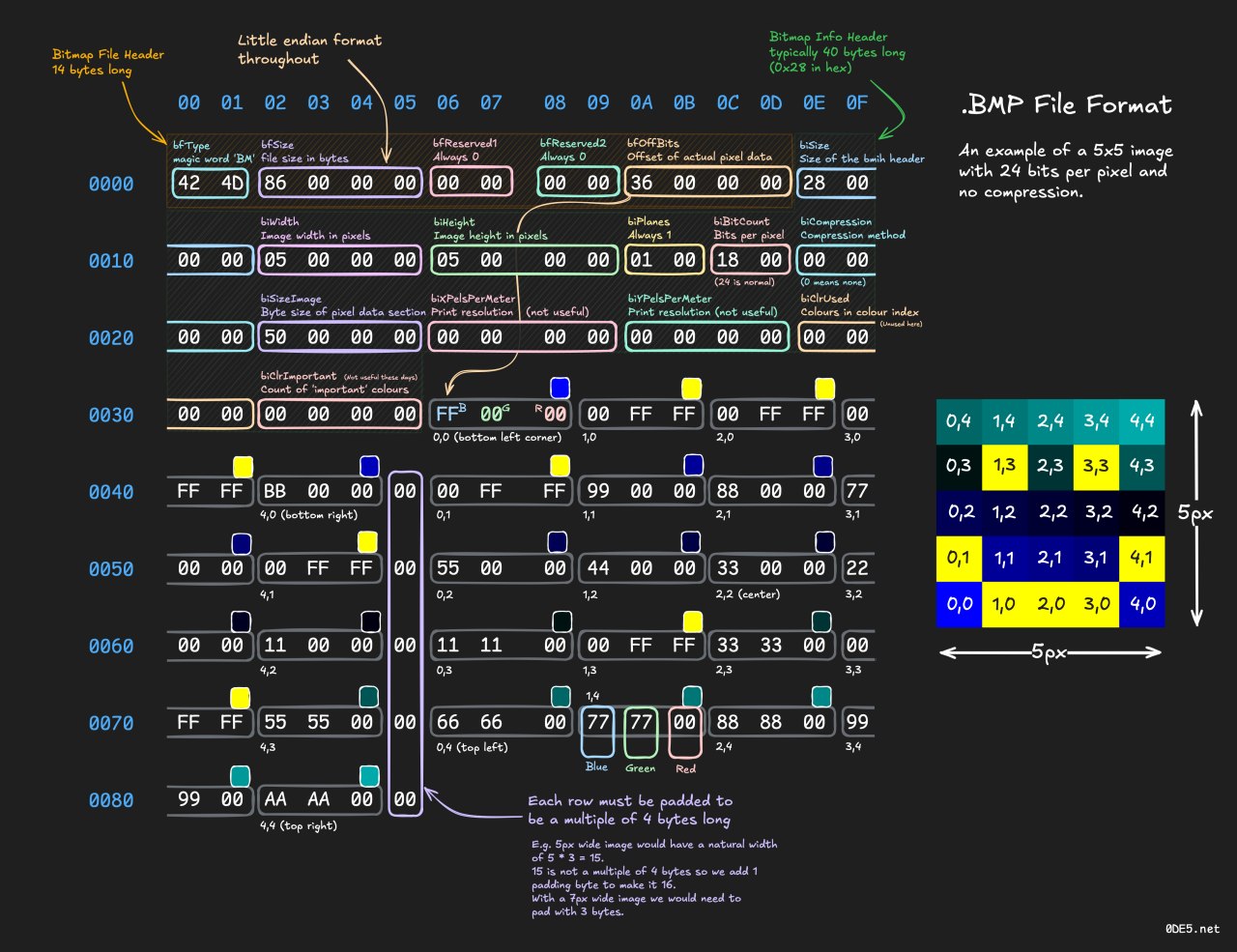
But common is not what my luck had prepared for me in this exercise. All because, when I was looking at the hex code, I found 7C 00 00 00 as the value for header size; which, in little endian notation is equal to 124 😐. And for does how are not familiar with simple inequalities (like me, for around 30 minutes of debuging before I noticed this part of the hex values) 40 is not equal to 124. And after some research, I was able to find out that the image I was using had a different type of bitmap header (more info here), which gave me something made sense:
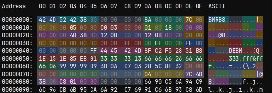
And by decoding the values of the image I’m using for testing:
| Offset | Bytes | Field | Decoded value |
|---|---|---|---|
0x00 | 42 4D | Signature | "BM" |
0x02 | 52 42 38 00 | File size | 3,686,994 bytes |
0x06 | 00 00 | Reserved 1 | 0 |
0x08 | 00 00 | Reserved 2 | 0 |
0x0A | 8A 00 00 00 | Pixel offset | 0x8A = 138 |
0x0E | 7C 00 00 00 | V5 header size | 124 |
0x12 | 00 05 00 00 | Width | 1280 px |
0x16 | C0 03 00 00 | Height | 960 px |
0x1A | 01 00 | Planes | 1 |
0x1C | 18 00 | Bits/pixel | 24-bit |
0x1E | 00 00 00 00 | Compression | BI_RGB / uncompressed |
0x22 | 00 40 38 00 | Image data size | 3,686,400 bytes |
0x26 | 12 0B 00 00 | X pixels/meter | 2834 ≈ 72 DPI |
0x2A | 12 0B 00 00 | Y pixels/meter | 2834 ≈ 72 DPI |
0x2E | 00 00 00 00 | Colors used | 0 |
0x32 | 00 00 00 00 | Important colors | 0 |
0x36 | 00 00 FF 00 | Red mask | 0x00FF0000 |
0x3A | 00 FF 00 00 | Green mask | 0x0000FF00 |
0x3E | FF 00 00 00 | Blue mask | 0x000000FF |
0x42 | 00 00 00 FF | Alpha mask | 0xFF000000 |
0x46 | 44 45 42 4D | Color-space type | PROFILE_EMBEDDED |
0x4A | 36 bytes | CIE endpoints | RGB color primaries |
0x6E | 00 00 00 00 | Gamma red | 0 |
0x72 | 00 00 00 00 | Gamma green | 0 |
0x76 | 00 00 00 00 | Gamma blue | 0 |
0x7A | 04 00 00 00 | Rendering intent | Images |
0x7E | 7C 40 38 00 | ICC profile offset | 0x38407C relative to V5 header |
0x82 | C8 01 00 00 | ICC profile size | 456 bytes |
0x86 | 00 00 00 00 | Reserved | 0 |
0x8A | … | Pixel data | starts here |
After doing the math, I found bytes after the 3,686,400 promised on the header; so I did some research and found that in the end there’s something called icc profile which tells the software how to deal with the color values, in such a way that the colors stay consistent between different devices. But I won’t go deeper into this topic just now because is out of the scope of the lab. Maybe it could be use it to hide the stego key, or some metadata regarding the extraction; but for now, let’s just finish here with the formating of the file.
Color encoding models
Before getting into LSB steganography, it helps to understand how pixel colors are actually stored.
RGB and RGBA
The most common color model for digital images is RGB.
Each pixel is represented using three color channels:
- R — Red
- G — Green
- B — Blue
Each channel is usually stored using one byte, which means it can contain a value from 0 to 255.
For example:
R = 255
G = 128
B = 64
In binary:
R = 11111111
G = 10000000
B = 01000000
Some image formats also contain an additional alpha channel:
RGBAThe alpha channel normally represents transparency.
A 24-bit image generally uses:
8 bits Red
8 bits Green
8 bits Blue
Therefore:
8 + 8 + 8 = 24 bits per pixelA 32-bit RGBA image normally uses:
8 bits Red
8 bits Green
8 bits Blue
8 bits Alpha
BMP channel order
An important detail is that BMP files normally store 24-bit pixel data in BGR order, rather than RGB order.
Conceptually, a pixel may be described as:
RGB = (R, G, B)but in the BMP file the bytes are normally stored as:
B G RFor example, the RGB pixel:
R = 120
G = 80
B = 200
would normally appear in the BMP pixel array as:
200 80 120Or actually in hex values as:
C8 50 78This distinction becomes important when modifying raw BMP bytes directly.
Row padding in BMP
BMP rows must normally have a size that is divisible by 4 bytes.
If the actual pixel data in a row is not divisible by four, extra padding bytes are added.
For a 24-bit BMP:
row_size = width × 3and the padded row size can be calculated as:
padded_row_size = (row_size + 3) & ~3which if we visualize in binary:
padded_row_size = (row_size + 00000011) & 11111100so if for example, row_size=10 first we add 3 (3 is the maximum padding, more than that would be negated by the bitwise AND operation):
  00001010
+ 00000011
----------
  00001101
And then the AND operation:
  00001101
& 11111100
----------
  00001100
Giving a final padded row size of:
padded_row_size = 00001100 = 12In this image:
width = 1280so:
1280 × 3 = 3840 bytesSince 3840 is already divisible by four, this image does not require additional row padding.
However, an implementation should not assume that this will always be the case.
YCbCr
RGB is not the only way of representing color, JPEG images commonly use a model called YCbCr. Instead of representing a pixel directly as red, green and blue, YCbCr separates the image into:
Y  = luminance / brightness

Cb = blue-difference chrominance

Cr = red-difference chrominance
This separation is useful because the human eye is generally more sensitive to changes in brightness than to small changes in color. JPEG compression takes advantage of this property. This becomes especially relevant for steganographic algorithms such as F5, because JPEG steganography does not normally modify raw RGB pixel bytes directly. Instead, information is embedded deeper inside the JPEG compression process. For simple LSB steganography with an uncompressed BMP, however, the RGB/BGR channel bytes themselves can be modified directly.
From color values to bits
Consider one color channel:
R = 154Its binary representation is:
154 = 10011010If the value changes from:
10011010to:
10011011the numeric value only changes from:
154 → 155The visual difference between those two channel values is extremely small.
The only bit that changed was the final bit:
1001101[0]
        |
        v
1001101[1]
That means every usable color-channel byte gives us a place where we can potentially store one bit of information, while changing the original channel value by at most 1.
That final bit has a name:
Least Significant Bit (LSB)
The Least Significant Bit, or LSB, is the rightmost bit of a binary number.
For example:
10011010
       ^
       LSB
The LSB contributes only:
2^0 = 1to the value of the byte.
Because changing it modifies a color-channel value by at most one, it provides a simple way of hiding information inside image pixels, by modifying the LSB of each byte to match the ones and zeros that describe the actual payload.
For example , let’s suppose I wanna hide the word fun. Each character is converted to ASCII:
| Character | ASCII | Binary |
|---|---|---|
f | 102 | 01100110 |
u | 117 | 01110101 |
n | 110 | 01101110 |
Which means the whole string to be encoded would be (we would need 28 bytes to hide our message):
01100110 01110101 01101110So, if we had the following random bytes:
    10110101 01100100 11001010 00110101 11100011 01010100 10011000 01111111
    11010101 00110010 10101000 11110000 01001111 10000100 01101001 11011010
    00111101 10110110 11101000 01010111 10010010 00101100 11111100 01000011
So we would need to do the following replacements:
| # | Original | Hidden bit | Encoded |
|---|---|---|---|
| 1 | 10110101 | 0 | 10110100 |
| 2 | 01100100 | 1 | 01100101 |
| 3 | 11001010 | 1 | 11001011 |
| 4 | 00110101 | 0 | 00110100 |
| 5 | 11100011 | 0 | 11100010 |
| 6 | 01010100 | 1 | 01010101 |
| 7 | 10011000 | 1 | 10011001 |
| 8 | 01111111 | 0 | 01111110 |
| 9 | 11010101 | 0 | 11010100 |
| 10 | 00110010 | 1 | 00110011 |
| 11 | 10101000 | 1 | 10101001 |
| 12 | 11110000 | 1 | 11110001 |
| 13 | 01001111 | 0 | 01001110 |
| 14 | 10000100 | 1 | 10000101 |
| 15 | 01101001 | 0 | 01101000 |
| 16 | 11011010 | 1 | 11011011 |
| 17 | 00111101 | 0 | 00111100 |
| 18 | 10110110 | 1 | 10110111 |
| 19 | 11101000 | 1 | 11101001 |
| 20 | 01010111 | 0 | 01010110 |
| 21 | 10010010 | 1 | 10010011 |
| 22 | 00101100 | 1 | 00101101 |
| 23 | 11111100 | 1 | 11111101 |
| 24 | 01000011 | 0 | 01000010 |
General, encodying a bit implies apply the 0xFE mask into the target byte, and then apply a logical OR wity the secret bit.
encoded_byte = (original_byte & 0xFE) | secret_bitThen, restoring the secret message consist on only looking at the final bit of the bytes, or applying the same mask 0xFE:
secret_bit = encoded_byte & 0xFEAnd this works fine in the current assignment; but, we need to think when was the last time someone sent you a bmp file, either by text, email, or IDK… usb sharing? Never? That’s what I thought hehe. Normally we see stuff like PNGs and JPEGs. Which implies some kind of compression, lossless and lossy respectibly. So hidding a message in such low value element, make’s the envelop really fragile, and using a kind of compression would make hard or imposible the task of recovering the message. For this, the method F5 was designed.
F5
F5 is a JPEG steganography algorithm proposed by Andreas Westfeld. The main idea is similar to LSB in the sense that we still want to make very small changes to some values, but the important difference is where those values live. With the BMP example I was directly modifying bytes that represented colors:
pixel -> B G R -> change one bitWith JPEG that is not really the data that finally gets stored in the file. Before being saved, JPEG does a bunch of transformations to the image. Maybe oversimplifying: it starts with RGB wich then is converted into YCbCr, this values are arranged in 8x8 blocks (separately for each channel), then the values of each of the 8x8 blocks would be described as multiple cosine waves by the DCT, then the values are quantized (or removing the high-frequency data), dividing the values by using standard tables defined regarding the type of compression/quality decired. And finally, Huffman encoding, to further compress the data. Returning a nice and well comprssed JPEG image.
Important: F5 works around the quantized DCT coefficients part of that process, rather than changing the final RGB pixels directly.
DCT coefficients
JPEG splits the image into small 8x8 blocks and applies something called the Discrete Cosine Transform, or DCT. Wich takes the 8x8 blocks and represent them as proportions of 64 (also 8x8) different cosine waves. After the DCT, every 8x8 block has 64 coefficients. The first one is normally called the DC coefficient, which represents a big part of the average value of the block. The other 63 are called AC coefficients, which represent progressively more detailed variations. Then JPEG quantizes those coefficients. In other words, it intentionally throws away some precision so the image becomes easier to compress.
So instead of thinking about pixels like:
120 80 200we can imagine having coefficients like:
-3 5 0 2 -7 1 0 0 ...Those are much closer to the values F5 actually works with, and most of them tend to be zero. And this is the first important difference with the BMP LSB example:
LSB on BMP -> modify pixel bytes
F5 on JPEG -> modify quantized DCT coefficients
This does not mean that F5 magically survives every possible JPEG recompression. If somebody decodes the JPEG and compresses it again, the DCT coefficients can change again. The point is that F5 embeds the information in the same domain JPEG itself uses while being compressed, instead of pretending a JPEG is just a bunch of stable RGB bytes.
So what does F5 actually change?
F5 mostly uses non-zero AC coefficients as places where information can be hidden. Wich varies between positive coefficients and negative coefficients. While for positive an even value represents 0 as the stego bit and an odd value represents 1 as the stego bit; for negative coefficients, the relationship is inverte, a negative even value represents 1 as the stego bit and a negative odd value represents **0 as the stego bit.
coefficient =  4 -> stego bit 0
coefficient = -4 -> stego bit 1
coefficient =  5 -> stego bit 1
coefficient = -5 -> stego bit 0
This is done to avoids creating an obvious asymmetry between the positive and negative sides of the coefficient histogram. If F5 needs to flip the hidden value of a coefficient, it decreases its absolute value by one. For example:
 5 -> 4
-5 -> -4
Both changes only move the coefficient one step toward zero.
That gives us another nice similarity with LSB:
- LSB: change a color value by at most 1
- F5: change the absolute value of a DCT coefficient by 1
But there is a small annoying case. Suppose the coefficient is 1 or -1. If F5 needs to modfiy it, it would turn the coefficients into zeros, which the method skips by default. This situation is called shrinkage.
Same result, but cheaper
Up to this point it could sound like F5 is not adding much, just doing something similar but in different channels, by the logic: message bit -> coefficient -> maybe change coefficient. But F5 actually does something way more interesting, wich actully reduce the amount of changes the actual algorithm do to the image, by implementing something defined as matrix encoding.
The easiest example is hiding 2 message bits inside 3 usable coefficient bits, while changing at most one of those three values.
Let’s call the three current steganographic bits:
a1 = 1
a2 = 0
a3 = 1
Instead of saying:
message bit 1 goes into a1
message bit 2 goes into a2
F5 calculates two values from the whole group:
x1 = a1 XOR a3
x2 = a2 XOR a3
With our values:
x1 = 1 XOR 1 = 0
x2 = 0 XOR 1 = 1
So the group:
1 0 1already represents the hidden message:
01and we don’t need to change anything. Now imagine we want to hide:
11Our current calculated value is:
01Only the first part is wrong. If we flip a1:
before: 1 0 1
after:  0 0 1
then:
x1 = 0 XOR 1 = 1
x2 = 0 XOR 1 = 1
and now the same three positions represent:
11with only one modification.
The nice part is that for this 3 -> 2 example there are only four possible
situations:
| What is wrong? | What F5 changes |
|---|---|
| nothing | nothing |
| only first hidden bit | a1 |
| only second hidden bit | a2 |
| both hidden bits | a3 |
The basic idea behind matrix encoding is that 2 secret bits can be stored inside three carrier bits, by only modifying one of the three carrier bits. For the genral case, F5 uses groups with n=2^k - 1 where:
kis the number of message bitsnis the number of usable coefficient positions
So for example:
Secret bits k | Coefficients n | Maximum changes |
|---|---|---|
| 1 | 1 | 1 |
| 2 | 3 | 1 |
| 3 | 7 | 1 |
| 4 | 15 | 1 |
| 5 | 31 | 1 |
This makes F5 more optimal, because it actually makes harder to detect changes by fully using the information in the image. As the group becomes larger, it can gide multiple bits while still normally changing at moest one coefficient in that group. Obviously there is a tradeoff. Using more coefficients for each chunk of the message lowers the amount of payload that fits in the image. But if the goal is to hide something without modifying the image more than necessary, that’s a pretty nice trade.
Don’t put all the changes in one place
There’s one more important idea in F5 called permutative straddling. Without permutation, if the algorithm simply started embedding from the first available coefficients and continued until the payload was fully embedded, the modifications could look like this:
[X][X][X][X][X][X][ ][ ][ ][ ][ ][ ]The changes are concentrated near the beginning, which can make the embedding pattern easier to detect. F5 avoids this by generating a pseudo-random permutation from the key. This permutation determines the order in which coefficients are visited. For example:
original positions:
1  2  3  4  5  6  7  8  9  10 11 12

permuted order:
8  2  11 5  1  9  4  12 6  3  10 7
Suppose the payload only needs the first 6 coefficients from that permuted order. F5 would therefore visit:
8 -> 2 -> 11 -> 5 -> 1 -> 9If we map those selected coefficients back to their original positions, the result looks like this:
positions:
[1][2][3][4][5][6][7][8][9][10][11][12]

selected:
[X][X][ ][ ][X][ ][ ][X][X][  ][ X][  ]
So instead of:
[X][X][X][X][X][X][ ][ ][ ][ ][ ][ ]we get something more spread out:
[X][X][ ][ ][X][ ][ ][X][X][ ][X][ ]The important point is that the coefficients themselves are not physically rearranged inside the JPEG. The permutation only changes the order in which F5 visits them. The receiver, using the same key, can generate the same permutation, visit the coefficients in the same order, and recover the hidden message.
And that’s enough F5 theory for what I want from this assignment. As mentioned at the beginning of this post, I’ll follow with a couple of metrics that are used to measure the relationship between the image before and after the mesage is stored.
PSNR
Now that I know how the message is being hidden, I need some way of measuring how different the resulting image is from the original one. The first metric from the assigment is PSNR, or Peak Signal-to-Noise Ratio.
To calculate PSNR we first need another value called MSE, or Mean Squared Error. MSE is basically the average error between the values of the original image and the values of the stego image.
For example, imagine only four values changed like this:
original = [100, 120, 200, 50]
stego    = [101, 120, 199, 50]
The difference between each pair is:
101 - 100 =  1
120 - 120 =  0
199 - 200 = -1
 50 -  50 =  0
If I just added those values, the 1 and -1 would cancel each other, even though two values actually changed. So MSE squares each difference before taking the average:
1²  = 1
0²  = 0
-1² = 1
0²  = 0
Giving:
MSE = (1 + 0 + 1 + 0) / 4
    = 0.5
So a smaller MSE means less difference between both images. If both images are exactly the same, then:
MSE = 0PSNR takes that error and converts it into a logarithmic value using:
PSNR = 10 * log10(MAX² / MSE)Where MAX is the largest possible value a channel can have. Since I’m working with 8-bit RGB values:
MAX = 255Using the previous example:
MSE = 0.5

PSNR = 10 * log10(255² / 0.5)
     ≈ 51.14 dB
Unlike MSE, with PSNR a bigger value means the images are closer.
The assigment specifically asks for PSNR >= 40 so I don’t really need to decide by eye whether the image “looks the same”. I can embed the message, calculate PSNR between the original and stego images, and check if the result is at least 40 dB. This metric also fits pretty nicely with LSB. As explained before, changing one LSB normally means changing a channel value by only 1, and sometimes we don’t need to change it at all because the bit already matches.
For example:
100 -> 101
200 -> 201
57  -> 57
88  -> 89
So even if I hide thousands of bits, each individual modification is still very small. That’s why I would expect the resulting PSNR to stay relatively high.
Important: There’s also one edge case: if both images are completely identical, then MSE = 0, meaning the formula would divide by zero. In that case PSNR is normally considered infinite, which just represents that there is no error between the images.
SSIM
PSNR is useful, but it only cares about the numerical difference between pixel values. It doesn’t really know if the change affected something visually important in the image. That’s where the second metric from the assigment comes in: SSIM, or Structural Similarity Index Measure.
The easiest way I found to think about the difference is:
- PSNR: how much did the pixel values change?
- SSIM: how similar does the structure of the image remain?
SSIM compares small areas of both images and mainly looks at three things:
- luminance: are they similarly bright?
- contrast : is the difference between dark and bright areas similar?
- structure: do the values change in a similar pattern?
For example, imagine this tiny grayscale block:
original:
100 102 104
101 103 105
102 104 106
After modifying some LSBs it could become:
stego:
101 102 105
101 102 105
103 104 107
A few values changed by 1, but the general pattern is almost exactly the same. The values still increase in basically the same direction, the brightness is almost identical, and there is no new edge or weird pattern in the block. So the SSIM should be very close to 1. Now imagine something much more destructive happened:
stego:
100 102 104
101 180 181
102 179 180
This is no longer just a couple of small numeric changes. Now there is a completely different structure in the middle of the block, and SSIM should decrease much more noticeably.
The actual formula is:
SSIM(x,y) = ((2*mu_x*mu_y + C1) * (2*sigma_xy + C2))
            ------------------------------------------------
            ((mu_x² + mu_y² + C1) * (sigma_x² + sigma_y² + C2))
Where, oversimplifying a little bit:
mu       -> average brightness
sigma²   -> variance / contrast
sigma_xy -> how similarly both regions vary
C1, C2   -> small constants to avoid unstable divisions
I’m not planning to calculate that by hand. What actually matters for the lab is how to read the result.
For identical images: SSIM = 1. And as they become less structurally similar, the value moves away from 1. So something like: SSIM = 0.9998 would mean the images are almost identical according to this metric, while SSIM = 0.96 still represents a pretty similar image, but with more noticeable structural differences.
Metric summary
So in the end both metrics are checking the same pair of images, but from slightly different angles:
| Metric | What I’m checking | Better result |
|---|---|---|
MSE | average numeric error | smaller |
PSNR | numeric error expressed as a signal/noise ratio | bigger |
SSIM | similarity of the image structure | closer to 1 |
Implementation
Well, with all of the theoretical part out of the way, let’s get dirty. The original idea was doing something in Rust 🦀; but after finding the BMP Image tutorial that I mentioned on the beginning of this post, I started using this piece of software ImHex, which was amazing to actually annalyze files’ raw data. Because of that, I decided to generate a plugin that contained 11 nodes for the Data Processor view.
In this part of the post, I’ll explain:
- The general structure of the plugin.
- Nodes documentation.
- Experiment with one image results.
General structure
The code is split into three layers, and each layer only talks to the one below it:
- Entry Point: Is located in the file
plugin_stegoooo.cpp. TheIMHEX_PLUGIN_SETUPmacro is part ofImHexSDK, and is the function the software actually call when it loads the.hexplugfile. The only goal of this function is to call oneregisterXxxxNodes()function per node file. - Nodes: Files located under the
content/nodes/folder. Each file defines it’s own node classes, and respectiveregisterXxxxNodes()function that callsContentRegistry::DataProcessor::add<NodeClass>("Stegoooo", "NAME_OF_THE_SPECIFIC_NODE"). This puts each node in the right place of theright-clickmenu in theData Processorview. The headers of theregisterXxxxNodes()functions is declared ininclude/content/nodes.hpp, which is the only header the entry point needs. - Helpers: Files located under the
content/helpers/folder. PlainC++functions that take and return a simpleImagestruct and byte vectors: decoding, color conversion, LSB, metrics, theBMPencoder, the random strings generator. Non of them have any dependency with theImHexSKD. TheImagestruct was created for this plugin, which uses thestb_imagelibrary to decodes the BMP into a raw pixel buffer, I don’t want to actually deal with the header stuff (while working theRustversion, this gave me way too much work).
Nodes
In general…
A Data Processor port can only be either a Buffer, an Integer or a Float. Theres no Image type, so images move between blocks as raw byts of the image file, and every block decodes its input with the decodeImage() function. This might generate a little bit overhead while running big structures; but, this is mainly for analisis, so I don’t think this is an actual problem.
The alternative was sending the different channels as individual buffers and the dimensions as integers, but that would give me alot of work while trying to generate the desired layouts.
Because the task was limited to BMP format, the decodeImage() checks the first two bytes for the BM signature and regects any other format; also, I’m defining STBI_ONLY_BMP which forces stb_image to compile it’s BMP reader.
Rendering vs. Processing
By design ImHex calls two method on each block, each on a different thread:
| Method | Thread | Allowed to |
|---|---|---|
process() | Data Processor worker | Read inputs, compute, set outputs, throw node errors |
drawNode() | Render (UI) thread | Draw ImGui widgets, create GPU textures |
This desing helps the GUI not freeze when a hevy compting task is being processed. The process() function keeps the results in a m_pending_... mutex, when done, it sets the m_hasPending flag into false; this way, the drawNode() will take the lock on the next cycle. There’s also the reset() function which resets the values the for the node and marks m_hasPending = true.
Color channel nodes
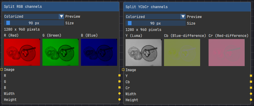
For the Split RGB channels and Split YCbCr channels nodes:
Inputs | Buffer, expecting image that can be turned into Image struct using decodeImage() |
Outputs | 3 different buffers for each of the respective channels (either RGB or YCbCr), width, and height of the inputted image |
Each one uses ImHex SDK texture function to display separately each of the respective channels, with a slider that can change the size of the display (min 90px and max 400px). This visualization work as native display objects; therefore, by hovering while holding the Shift key, there will be a bigger display of the image.
Following the general design this nodes recieve the full image buffer and process it into the Image struct.